Tactic-toe (Firmware)
Please first see the overview article to learn about tactic-toe
Firmware
After using Python, the next step is to make it run on a microcontroller. Unlike running the algorithm on a PC, an MCU is much more limited in RAM/ROM resources. Not only that, the microcontroller also has to interface the RGB LEDs and touch sensors.
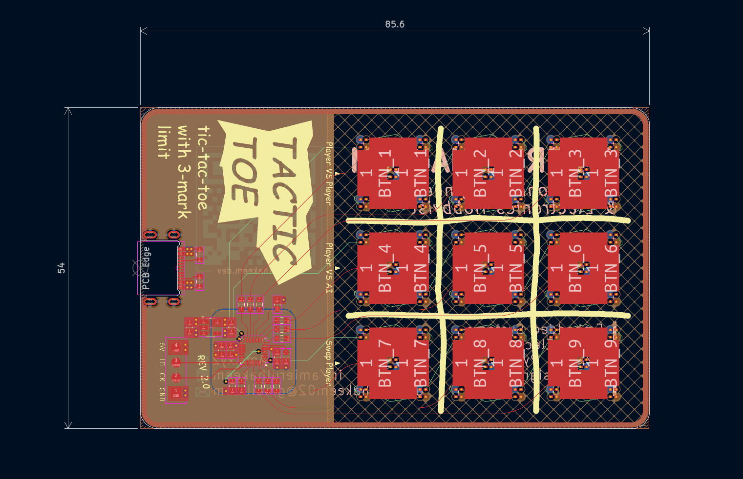
This article covers how the firmware for the PCB version of tactic-toe is designed.
Tactic-toe AI
I encourage you to first read the software article to get the full context.
In short, I solved tactic-toe by brute forcing exploring every possible game state and from the end game state, working backwards to figure out the best moves. I decided not to manually code a custom strategy algorithm because it doesn’t guarantee that it will play perfectly. Plus, the brute force method generalizes better.
Few key facts from the software section:
- There are 16030 unique game states (after symmetry optimization)
- Each state has been assigned a score from 0 to ±16
- 0 means its a draw
- +16 means X will win
- -16 means O will win
- Anything in between determines the amount of moves for the player to win
- For example: +13 means X will win in 3 moves
To find the best move for a given state, just lookup the all next possible states (child states) and choose the child state with the most favourable score.
Limitations
The chosen MCU is STM32G042G6U6 with only 6KB RAM and 32KB Flash (ROM).

To make the AI, your first thought might be to just store the best move for all the possible states into flash. So, for every state, you need to store the state and the best move itself. The AI algorithm then just looks for the state in memory and just grabs the best move.
This wouldn’t be a problem if you have enough memory to store all the precalculated states and moves. Given that there are 16030 states, and 32KB of flash, you need to store a single state-move pair in under 2 bytes to fit. That’s not even accounting for the rest of the program size which easily will take up a few KBs at least.
Encoding game state in the minimum amount of bytes
To see if its even possible to store all the precalculated moves in under 32KB, we have to first figure out how many bytes do we need to store a game state.
Attempt 1
Tactic-toe board has 9 squares and each of the squares can either be X or O. However, each of the symbols can only stay on the board for only 3 moves. So, let’s assign a number to the amount of “life” left for a symbol, and use (+ve) for X and (-ve) for O.
Therefore, a square can either be ±3, ±2, ±1, or 0 (empty).
The way I think about this representation is when a move is played, all of the current player’s symbols on board will all be reduced by 1 and if it goes to 0 it becomes an empty square. This is in fact how I programmed the game logic.
As a result, there are 9 squares, each with 7 possible states. The 7 different states require at least 3 bits (2^3 > 7). Then, Multiplied by 9 squares, 27 bits minimum, or 4 bytes (since memory are in bytes rather than in bits).
Not to forget, you also need to store whose turn it is to move, but that can be fit in one of the extra empty bit.
With 4 bytes per state, you can only fit 8000 states in a 32KB storage. Surely, we can do better than this.
Attempt 2
In the previous attempt, I stored each of the squares content where at least 3 of them will be empty which is a waste of memory space. So, how about instead, we store the position of each symbol (with its corresponding “life”) since there will only be one of each.
There are only 6 symbols (3 life for each X and O) positions to be stored. Each position can only be in either 9 squares. You would need only 4 bits to store 9 unique positions, so 1 byte can store positions for 2 symbols.
Therefore, the entire board can be stored with only 3 bytes.
For example, given a board below:
// -3 |   | -1
// ---+---+---
//    | 3 | 1
// ---+---+---
//    | 2 | -2

uint8_t positionArr[9];

positionArr[0] = 0; // -3
positionArr[1] = 8; // -2
positionArr[2] = 2; // -1
positionArr[3] = 5; // 1
positionArr[4] = 7; // 2
positionArr[5] = 4; // 3
The game state can then be encoded as shown below:
uint8_t encodedBytes[3];

encodedBytes[0] = (positionArr[0] & 0x0F) << 4 | positionArr[1];
encodedBytes[1] = (positionArr[2] & 0x0F) << 4 | positionArr[3];
encodedBytes[2] = (positionArr[4] & 0x0F) << 4 | positionArr[5];
This approach saves 1 byte from the previous method. That doesn’t sound a lot (from 4 bytes to 3 bytes) but for the same memory space we can +33% more states can be stored.
One caveat with this, is that the current player’s turn is not encoded. So there is no way to differentiate who’s turn it is given the encoded bytes. You could add 1 more byte just for it, but instead I used a better way which will be explained in the minimax section.
Theoretical Value
With 16030 unique states, in theory, you only need 14 bits (2^14 = 16384) to represent each unique state. However, there is no easy way to encode/decode a given state to a single unique index value.
There might be a way to do so but that might just involve super complex compression algorithm or something idk, but I’m just saying its theoretically possible. One possibility is the encode/decode function will be so long that in the end it takes up more memory to store the function.
There might also be another more clever and easy way to encode the state in less than 3 bytes but so far the ones I found are just not worth the extra effort to save a few more bits where in the end 32KB will just not going to be able to fit all 16030 different states.
Minimax
Given now the best attempt to store a board state requires a minimum of 3 bytes each. It is pretty much impossible to just store all of the states with their corresponding best moves. I have actually thought of adding an external 1MB EEPROM just to store all the moves, but I found a better solution.
Remember our old friend? Minimax.
The main issue with minimax (previously explored in software article) is that there are no way to evaluate a given position other than checking for a winning condition. Thus, the algorithm simply goes in a loop infinitely. Terminating with a depth limit caused incorrect evaluation and non-optimal moves to be made.
Now however, we have all the possible states each with their own corresponding scores. So, what if we use the precalculated states’ scores as the score to evaluate a state in minimax. This would work obviously with all the state scores, but since we can’t store all states in memory.
So, the strategy I came up with is to only store the states that are far from winning (most amount of moves to reach a win), since they require a lot of depth to be searched fully.
This code snippet shows how this works:
uint8_t transformIndex;
TTT_StateEntry *foundEntry = searchEntry(board, &transformIndex);

if (foundEntry != NULL){
    if (player == TTT_PLAYER_X){
        if (foundEntry->score_x != 0x7F)
            return foundEntry->score_x + depth;
        else
            Error_Handler();
    }
    else {
        if (foundEntry->score_o != 0x7F)
            return foundEntry->score_o - depth;
        else
            Error_Handler();
    }
}
After minimax checks for winning conditions, it runs this code. It first checks if there is a precalculated score for the board is stored in memory. If there is, return the score plus its depth (to prioritize moves that get quicker to the given state). Ox7F was intentionally chosen as “invalid” number because the score can range from -16 to +16 including 0.
After testing this and fixing a lot of bugs along the way, at one point it was working quite well, but it was still failing some edge cases for some reason. Debugging this on a microcontroller was definitely a challenge.
Final Implementation
I changed a bunch of stuff at the end and honestly, I am not sure which exactly that fixes the edge cases problem. But, I think what fixes it was the fix I made for the python code that generates the precalculated moves and exports it to a header file.
To put simply, there was a bug when I am filtering for the states that will be exported. I had 2 functions, one that detects for duplicates and one filters states based on its scores. I messed up the order the function where it caused some of the states filtered before it should and causing incomplete state data.
The output of the python file is shown below:
Optimising...
1. Removed terminal states -> 16030 to 14518 (-1512)

2.0 Removed states that is 0 moves to winning -> 14518 to 14518 (-0)
2.1 Removed states that is 1 moves to winning -> 14518 to 9676 (-4842)
2.2 Removed states that is 2 moves to winning -> 9676 to 8736 (-940)
2.3 Removed states that is 3 moves to winning -> 8736 to 6874 (-1862)
2.4 Removed states that is 4 moves to winning -> 6874 to 5999 (-875)
2.5 Removed states that is 5 moves to winning -> 5999 to 4299 (-1700)
2.6 Removed states that is 6 moves to winning -> 4299 to 3829 (-470)
2.7 Removed states that is 7 moves to winning -> 3829 to 3062 (-767)
2.8 Removed states that is 8 moves to winning -> 3062 to 2638 (-424)
2.9 Removed states that is 9 moves to winning -> 2638 to 2325 (-313)

Found 82 duplicate pairs (same board, diff turn)
3. Removed duplicate states -> 2325 to 2284 (-41)
The final amount of states that was stored is actually only 2284 states.
Each of the states is stored in an array of 6 bytes, and exported to a header file tactictoe_states.h:
- Bytes 0 to 2 -> Encoded canonical state,
- Bytes 3 -> Best move 4 MSB for x, 4 LSB for o
- Bytes 4 -> Score for the state (X’s turn)
- Bytes 5 -> Score for the state (O’s turn)
- The array is pre-sorted (big-endian)
Bytes 4 to 5 couldve actually been optimized to a single byte like how byte 3 splits 4 bits for X and 4 bits for O.
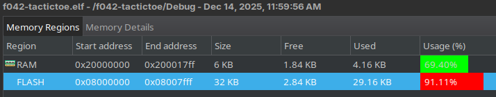
The code is compiled with -Oz (optimize for size). There is only 2.84 KB Flash left. The precalculated states array alone takes up 13.38 KB, which is almost half of the 32 KB Flash.
Result
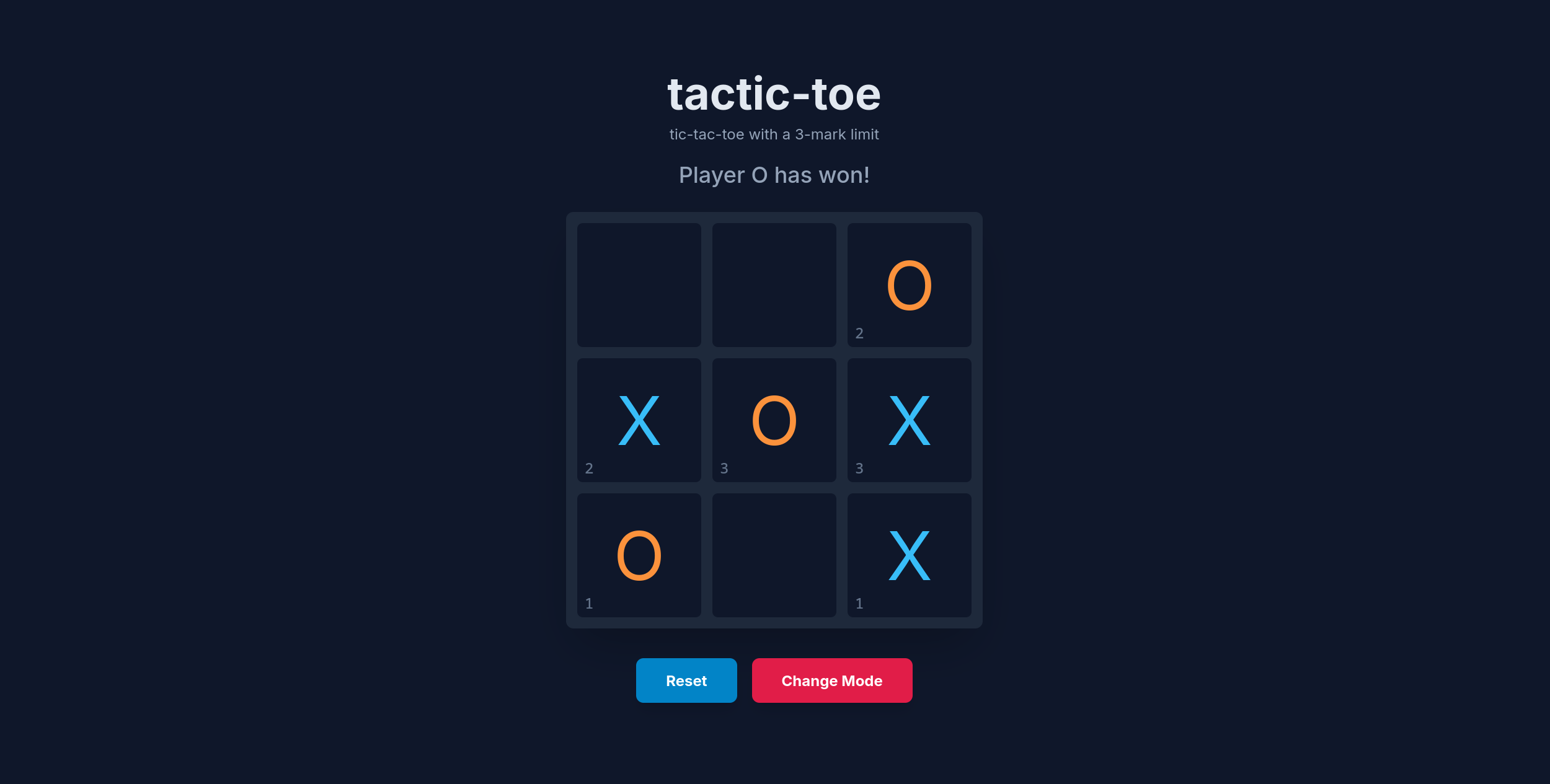
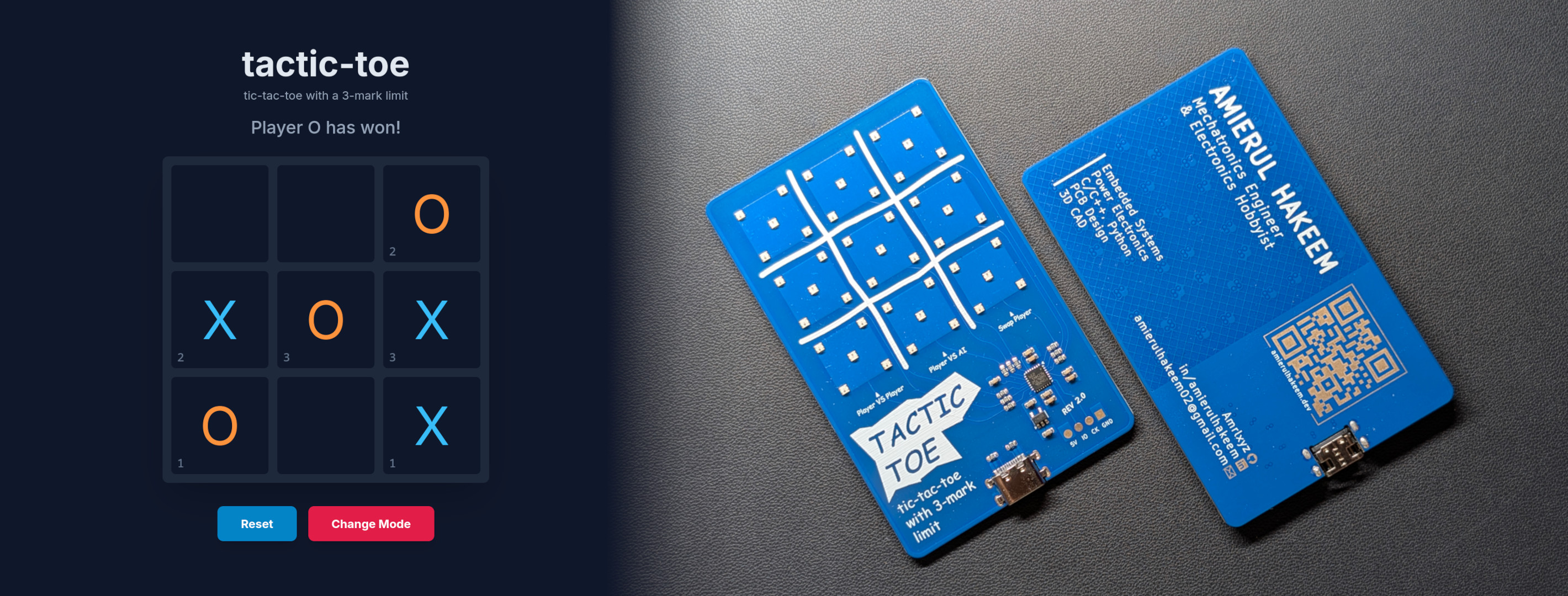
Even with only 2284 states stored in memory, the AI plays perfectly. I verified it’s moves by playing it against the online version of tactic-toe, which plays the game perfectly.
I can proudly say, I made the perfect tactic-toe AI run on a microcontroller with limited memory.
Move Randomizer
On top of the making the AI play perfectly, I also wanted to make it play random moves if the move results in the same position symmetrically. However, there is only one best move stored in the precalculated states array. To get around this, we can utilize the symmetry to generate all the possible best moves by comparing the resulting state.
The bigger problem is, there are no Random Number Generator (RNG) on this MCU. Unlike most high level systems you can call a function that will generate a true random number, the MCU don’t have the hardware to do so.
What I did is, by using an unused ADC channel to sample voltage since it will be affected by electrical noise. In this case, I used the internal temperature sensor channel and sample its voltage, then use a modulo operator to get an index to choose random item from an array.
randSeed = HAL_ADC_GetValue(&hadc);

bestMove = symMoveList[randSeed % symMoveIndex];
RGB LEDs
The RGB LEDs I used are SK6805-EC15 in V1 and XL-1615RGBC-2812B-S in V2. The controller embedded inside the LEDs are actually SK6805 and 2812B respectively. They are in fact very popular among addressable RGB LED markets with various package sizes and shapes, but the controllers are the same.
This is relevant because of how they are controlled. They both share very similar protocol.
PWM to send digital data
If you say PWM, the last thing I would have thought is that PWM for digital data transfer. Surprisingly, it is actually common to use PWM to send digital data to RGB LEDs, and indeed this is what I used. Sure, PWM are also used for some servos to send position data, but in that, the position is determined by duty cycle, whereas in this, actual bits are transferred using PWM.
Fundamentally, PWM is actually just a timer peripheral with a counter period to set the duty cycle.
SK6805 and 2812B both uses an interesting way to transmit 1s and 0s. With a fixed period from the datasheet, the duty cycle determines if its either 1 or 0. The way I think of it is like UART, it is async with a fixed baud rate, but instead of HI and LO determines 1 and 0, it is determined by duty cycle. Then to stop, a long pulse of 0 is sent. The waveforms are shown below:
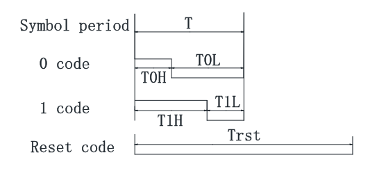
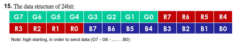
With 24 bits, you can define Red, Green, Blue, brightness individually. If, more than 24 is sent, the next bits are passed down in the daisy chain of RGB LEDs. Then, by using a timer with DMA simplifies data transmission quite a lot.
For a much better explanation on the protocol and how to implement it on CubeIDE, I used this video from one of my favourite YouTuber:
The major difference between the two LED controllers are just the bit timings, otherwise they are identical. Both have the same minimum period, 1.2 us (833.3 kHz). With 15 LEDs in a daisy-chain on this design, and each requires 24 bits + 1 reset bit (200 us for 2812), the theoretical update rate is 1.8 kHz (632 us). This is very fast, so the LEDs are only updated when there are new changes to the board to minimise the noise that can affect the touch sensors sensitivity.
Touch Sensors
The PCB touch sensors uses an on-chip touch controller peripheral called Touch Sensing Controller (TSC). Unlike other more common peripherals, the TSC are pretty limited in terms of resources online. There are application notes and references but they are not beginner-friendly.
Touch Sensing Controller (TSC)
Typically, to use any STM32 hardware peripheral, I would first refer the STM32 chip reference manual to read on how the peripheral actually works, and hardware registers to use. Then after getting an idea, I would refer to the STM32 HAL manual to find the functions that can do all the low-level register configs for me.
However, for TSC, there is another layer on top of HAL that can help with the development. This is called the TouchSensing library by STM32. This abstracts away a lot of complexity from the HAL layer and adds on built-in extra features, like debouncing, auto calibration which is very good for this project.
The problem is, the documentation on this is very limited. There is a user manual UM1913, but it’s a super long PDF with no clear guide to just get something simple working. It is great for very detailed description but for me who just wants something simple to test, it’s just very overwhelming.
At the end, I managed to get something basic working by referring to a sample code from another STM32 discovery board with an onboard touch sensor pad.
Interrupts with TouchSensing library
Ideally, you would want the TSC hardware to sample in the background with interrupts, so it wouldn’t slow down the main code execution. The TS Library does provide an interrupt sampling function called tsl_user_Exec_IT() but trying to get it to work reliably was a challenge. Again, this was mainly due to me just doing trial and error rather than going through the user manual properly (but that’s boring).
Then, I found this video on a lab example for the TouchSensing library. It helped on how to set up the peripheral, but it still doesn’t explain how to use the interrupt version of the library.
Finally, after a lot of trial and error, the way I implemented tsl_user_Exec_IT() is by having a timer interrupt that runs the function at a fixed frequency. It ended up working very well. I think the problem before was because the touch sensing function was running with an inconsistent timing between polls causing it to break some functionalities.
I have no way of verifying if this is the intended way to achieve interrupt polling, but I guess if it works don’t fix it.
Other Stuffs
There are a bunch of other smaller things I considered and problems in the project, but it would be impossible to mention all of them. So here are some of my favourites.
GPIO Pins Utilization
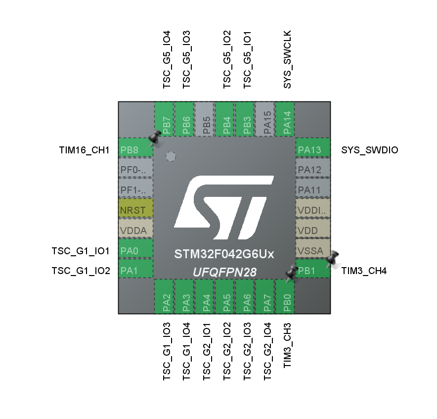
At the end, only 6 out of 28 pins was left unused. I think this is the first time that I have used up almost all of the pins on a microcontroller. Typically, you would only use a few of them. Making sure every pin have the required functionality and optimizing for PCB routing difficulty was quite a challenge.
USB Support
Since I am using a USB-C connector I thought it would be cool if it could also add an extra functionality, perhaps adding the option to re-flash the firmware through USB. Unfortunately the USB stack uses too much flash storage, and it would be impossible to have both USB software and the tactic-toe states at the same time.
Actually in the first version of the PCB, the USB data lines were connected to the MCU but after realising the flash storage issue, it was removed in the second version. Plus, its probably for the best since someone can view it as a security risk if they connect it to a PC.
BOOT0 Programming bit
When I first programmed the board with an ST-Link, it works as expected. However, when I disconnected the ST-Link and power it with USB, it just stopped working. I thought it might have been a USB-C connector issue but when I measure the voltage rails, the 5V and 3V3 rails are both fine. So, after some troubleshooting, I found out the issue.
Typically, with most STM32 microcontrollers with higher pin counts, you will get BOOT0 and BOOT1 pin that determines from which memory it should boot from. It allows user to boot from user flash, system memory or even from embedded SRAM.
One practical use of this is it allows for the MCU to boot from a bootloader and allows for reprogramming of flash. Then, after the new program is flashed, you can boot normally from flash memory. In fact, this is how it’s typically done with STM32 dev boards if you are trying to program the board without using a debugger.
This is typically not a problem, but since the F042 that I’m using had is in a small package, there are no BOOT pins. Instead, it uses special bits to determine boot modes. Specifically for the F042 series I’m using, there 3 programmable bits to select boot option:
- nBOOT1
- BOOT_SEL
- nBOOT0
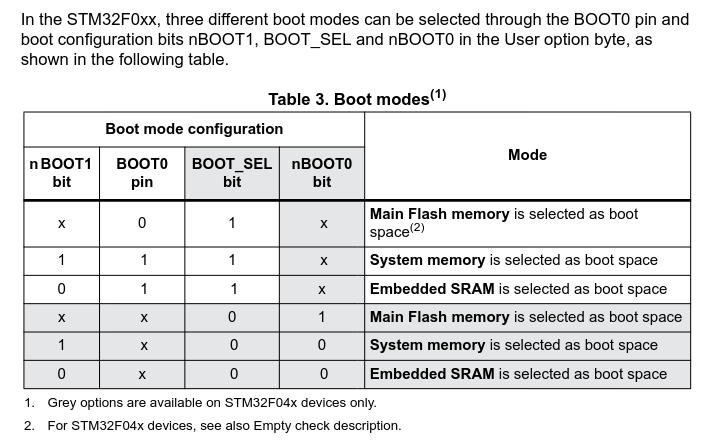
image taken from AN4080
Despite BOOT0 pin shown in the table, there was no BOOT0 pin on the actual IC. My guess that it’s not available for lower pin count packages.
Turns out, the F042 IC comes with all the BOOT bit set to 1. This resulted in the MCU always defaults to booting to system memory when powered on. System memory contains the embedded bootloader by STM32, whereas my program was flashed to the main flash memory.
The fix is simple, you just have to use STM32CubeProgrammer to set the BOOT_SEL bit to 0:
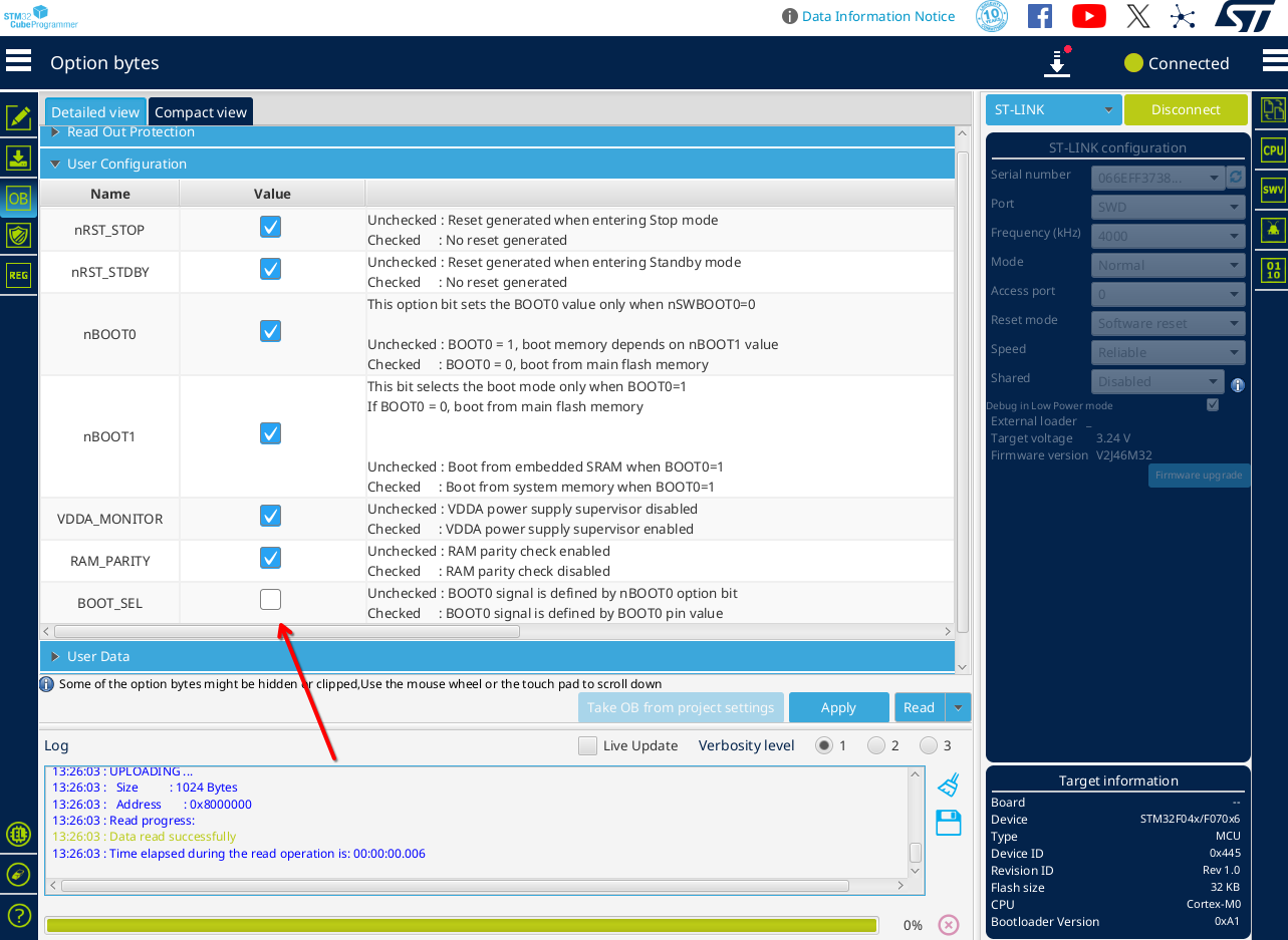
Now, after being powered by USB, it boots to main Flash and it works as expected. It’s only a one time thing and the next time its flashed using CubeIDE, the BOOT bit doesn’t get reset.
Source Code
All the code is open source on my GitHub.
Link to the GitHub repo: github.com/Amrlxyz/f042-tactictoe
If you are interested in adding new features, feel free to contact me or just make a PR.